- 您现在的位置:买卖IC网 > Sheet目录311 > AS5140 PB (ams)BOARD PROGRAM AS5140
�� �
�
�AS5140H�
�Data� Sheet� -� D� e� t� a� i� l� e� d� D� e� s� c� r� i� p� t� i� o� n�
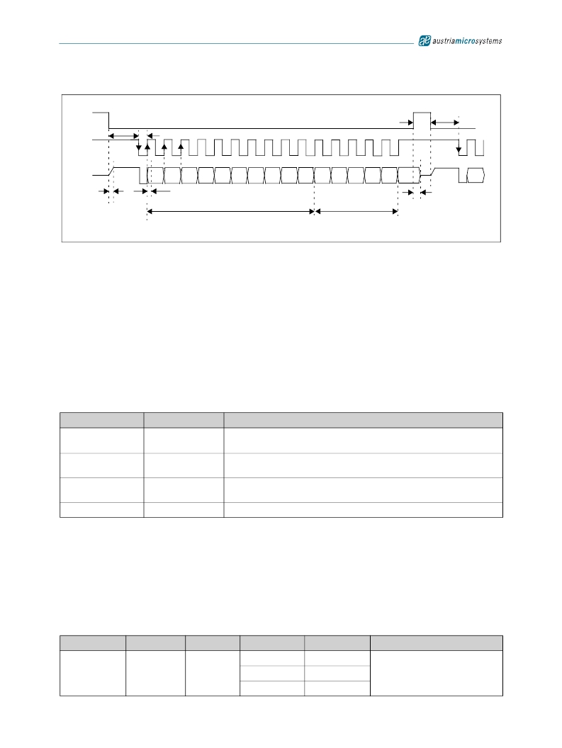
�Figure� 5.� Synchronous� Serial� Interface� with� Absolute� Angular� Position� Data�
�CSn�
�t� CLK FE�
�T� CLK/2�
�t� CSn�
�t� CLK FE�
�CLK�
�1�
�8�
�16�
�1�
�DO�
�D9�
�D8�
�D7�
�D6�
�D5�
�D4�
�D3�
�D2�
�D1�
�D0�
�OCF� COF�
�LIN�
�Mag� Mag�
�INC DEC�
�Even�
�PAR�
�D9�
�t� DO� active�
�t� DO� valid�
�Angular� Position� Data�
�Status� Bits�
�t� DO� Tristate�
�Data� Content�
�D9:D0� –� Absolute� angular� position� data� (MSB� is� clocked� out� first).�
�OCF� –� (Offset� Compensation� Finished).� Logic� high� indicates� the� finished� Offset� Compensation� Algorithm.� For� fast� startup,� this� bit� may� be� polled�
�by� the� external� microcontroller.� As� soon� as� this� bit� is� set,� the� AS5140H� has� completed� the� startup� and� the� data� is� valid� (see� Table� 17)� .�
�COF� –� (Cordic� Overflow).� Logic� high� indicates� an� out� of� range� error� in� the� CORDIC� part.� When� this� bit� is� set,� the� data� at� D9:D0� is� invalid.� The�
�absolute� output� maintains� the� last� valid� angular� value.� This� alarm� may� be� resolved� by� bringing� the� magnet� within� the� X-Y-Z� tolerance� limits.�
�LIN� –� (Linearity� Alarm).� Logic� high� indicates� that� the� input� field� generates� a� critical� output� linearity.� When� this� bit� is� set,� the� data� at� D9:D0� may� still�
�be� used,� but� can� contain� invalid� data.� This� warning� may� be� resolved� by� bringing� the� magnet� within� the� X-Y-Z� tolerance� limits.�
�MagINCn� –� (Magnitude� Increase)� becomes� HIGH,� when� the� magnet� is� pushed� towards� the� IC,� thus� increasing� the� magnetic� field� strength.�
�MagDECn� –� (Magnitude� Decrease)� becomes� HIGH,� when� the� magnet� is� pulled� away� from� the� IC,� thus� decreasing� the� magnetic� field� strength.�
�Signal� “HIGH”� for� both� MagINCn� and� MagDECn� indicate� a� magnetic� field� that� is� out� of� the� allowed� range� (see� Table� 16)� .�
�Table� 16.� Magnetic� Magnitude� Variation� Indicator�
�MagINCn�
�0�
�0�
�1�
�1�
�MagDECn�
�0�
�1�
�0�
�1�
�Description�
�No� distance� change�
�Magnetic� Input� Field� OK� (in� range)�
�Distance� increase:� Pull-function.� This� state� is� dynamic,� it� is� only� active� while� the� magnet�
�is� moving� away� from� the� chip� in� Z-axis.�
�Distance� decrease:� Push-� function.� This� state� is� dynamic,� it� is� only� active� while� the�
�magnet� is� moving� towards� the� chip� in� Z.-axis.�
�Magnetic� Input� Field� invalid� –� out� of� range:� Too� large,� Too� small� (missing� magnet).�
�Note:� Pins� 1� and� 2� (MagINCn,� MagDECn)� are� open� drain� outputs� and� require� external� pull-up� resistors.� If� the� magnetic� field� is� in� range,� both�
�outputs� are� turned� off.�
�The� two� pins� may� also� be� combined� with� a� single� pull-up� resistor.� In� this� case,� the� signal� is� high� when� the� magnetic� field� is� in� range.� It� is� low� in� all�
�other� cases� (see� Table� 16)� .�
�Even� Parity� –� A� bit� for� transmission� error� detection� of� bits� 1to� 15� (D9� to� D0,� OCF,� COF,� LIN,� MagINCn,� MagDECn).�
�The� absolute� angular� output� is� always� set� to� a� resolution� of� 10� bit.� Placing� the� magnet� above� the� chip,� angular� values� increase� in� clockwise�
�direction� by� default.� Data� D9:D0� is� valid,� when� the� status� bits� have� the� following� configurations:�
�Table� 17.� Status� Bit� Outputs�
�OCF�
�COF�
�LIN�
�MagINCn�
�MagDECn�
�Parity�
�0�
�0�
�1�
�0�
�0�
�0�
�1�
�even� checksum� of� bits� 1:15�
�1�
�0�
�www.austriamicrosystems.com/AS5140H�
�Revision� 1.4�
�13� -� 37�
�发布紧急采购,3分钟左右您将得到回复。
相关PDF资料
ASDMB-ADAPTER-KIT
ASDMB MEMSPEED P II OSC KIT
ASFLMPLP-ADAPTER-KIT
ASFLMPLP MEMSPEED P II OSC KIT
AT24C01-10SI-1.8
IC EEPROM 1KBIT 400KHZ 8SOIC
AT24C01B-TSU-T
IC EEPROM 1KBIT 1MHZ SOT23-5
AT24C02C-XHM-B
IC EEPROM 2KBIT 1MHZ 8TSSOP
AT24C04AN-10SI-2.7
IC EEPROM 4KBIT 400KHZ 8SOIC
AT24C08B-PU
IC EEPROM 8KBIT 1MHZ 8DIP
AT24C1024B-TH25-B
IC EEPROM 1MBIT 1MHZ 8TSSOP
相关代理商/技术参数
AS51400FLF
制造商:TT Electronics / IRC 功能描述:AS51400FLF
AS51400HLF
制造商:TT Electronics / IRC 功能描述:AS51400HLF
AS51400JLF
制造商:TT Electronics / IRC 功能描述:AS51400JLF
AS51401FLF
制造商:TT Electronics / IRC 功能描述:AS51401FLF
AS51401HLF
制造商:TT Electronics / IRC 功能描述:AS51401HLF
AS51401JLF
制造商:TT Electronics / IRC 功能描述:AS51401JLF
AS51402FLF
制造商:TT Electronics / IRC 功能描述:AS51402FLF
AS51402HLF
制造商:TT Electronics / IRC 功能描述:AS51402HLF